1. Key Features
- 190-840nm broadband coverage: Spans UV to visible for UV absorption, visible color, transmittance, reflectance and light source spectral measurement.
- High-sensitivity professional structure: Built-in order-sorting filter and enhanced cylindrical lens balance stray-light suppression and weak-light collection.
- 2048-pixel Hamamatsu detector: Hamamatsu S11639-2048Q for high-sampling-point UV-VIS measurement.
- Stable circuitry and anti-interference design: Low-noise board supports long-term online acquisition across multiple units - ideal for lab platforms and online analyzers.
- Multiple communication interfaces: Type-C, RS232, RS485 with optional USB standard, USB extended and Modbus protocols.
- Temperature monitoring and drift compensation: Onboard sensor and drift compensation maintain spectral consistency over long runs.
2. Specifications
2.1 Technical Parameters
| Item | Parameter |
|---|---|
| Model | SPEC-CDS350 |
| Type | Broadband high-sensitivity professional fiber spectrometer |
| Wavelength range | 190-840nm (default, configurable) |
| Optical resolution | 0.3-3.2nm (configuration dependent) |
| Wavelength accuracy | Typ. +/-0.01nm |
| Signal-to-noise ratio | 350:1 |
| Slit size | 50μm default; 10μm, 25μm, 100μm, 200μm optional |
| Detector | Hamamatsu S11639-2048Q |
| Optical interface | SMA905 |
| Communication | Type-C / RS232 / RS485 |
| Protocols | USB standard / USB extended / Modbus (serial) optional |
| Built-in sensor | Temperature sensor |
| Drift compensation | Built-in |
| Power | 5V / 0.3A |
| Dimensions | 100mm x 65mm x 33mm |
| Weight | Approx. 300g |
2.2 Appearance and Dimensions
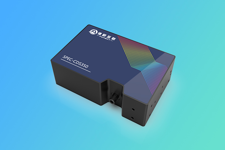
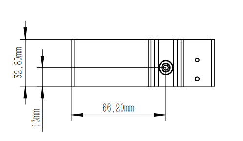
3. Common Setups
The SPEC-CDS350 targets UV- and visible-focused fiber spectroscopy; build transmittance, reflectance, integrating sphere and fluorescence paths per sample type.
| Setup | Typical configuration | Main use |
|---|---|---|
| UV absorption | Deuterium or xenon flash lamp + cuvette holder | Solution UV absorption, concentration, transmittance |
| Visible transmittance | Continuous source + cuvette holder | Dyes, solutions, filters and transparent materials |
| Source testing | Source + integrating sphere or fiber input | Spectral lines and distribution of LEDs, xenon and deuterium lamps |
| Surface reflectance | Source + reflectance probe | Color, coatings, paper, plastics and material surfaces |
| Solid transmittance | Source + solid transmission holder | Films, lenses, windows and optical materials |
| Fluorescence | Excitation source + reflectance probe or sphere | Fluorescence emission spectra and material screening |
4. Principle
4.1 Fiber spectrometer composition
Fiber spectrometers typically use a Czerny-Turner optical layout. Polychromatic light from an external source, sample or probe enters through the SMA905 interface; the entrance slit defines the beam, which is then dispersed by a collimating mirror, grating and focusing optics onto different pixels of a linear array detector. Each pixel corresponds to a wavelength band; after ADC conversion and wavelength calibration, the software reconstructs the wavelength-ordered spectrum.
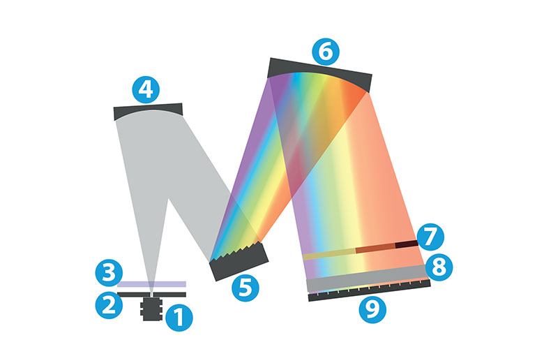
Typical components:
| Component | Function |
|---|---|
| Input interface | Connects fiber and aligns to the entrance slit for repeatability and mechanical strength |
| Slit | Controls throughput; affects sensitivity and optical resolution |
| Long-pass or balancing filter | Filters short-wave stray light per band and application; improves spectral response uniformity |
| Collimating mirror | Converts diverging slit light into a collimated beam onto the grating |
| Grating | Disperses light by wavelength - the core element for range and resolution |
| Order-sorting filter | Suppresses overlap of second- and higher-order diffraction with first-order spectra - especially important for broadband instruments |
| Cylindrical lens or focusing group | Focuses the dispersed band onto the detector active area, improving energy utilization |
| Linear array detector | Pixels receive different wavelengths and convert them into digitizable electrical signals |
The SPEC-CDS350's UV-VIS capability comes from the combined grating, slit, filter and detector configuration. Selection balances wavelength range, resolution and sensitivity: more grating lines raise resolution but narrow the range; wider slits raise signal but lower resolution; for UV bands, confirm the transmittance of sources, fibers, cuvettes and window materials.
5. Applications
- UV-VIS absorption: absorbance of chemical solutions, dyes, reagents, pharmaceuticals and water samples.
- Optical transmittance: filters, lenses, films, plastic sheets, glass and coating materials.
- Light source spectra: peak wavelength, FWHM and distribution of LEDs, UV lamps, xenon and deuterium lamps.
- Color and reflectance: surface color, reflectance, whiteness and coating differences.
- Online analyzers: RS485 or Modbus connection to production lines, lab platforms or automated monitoring equipment.
- Fluorescence and weak-light: fluorescence emission spectra in the visible band with suitable excitation sources and accessories.
6. Selection and Configuration
6.1 SPEC-CDS350 vs SPEC-CMS960
| Model | Default range | Recommendation |
|---|---|---|
| SPEC-CDS350 | 190-840nm | Prefer when focused on UV, visible and short-wave NIR up to 840nm |
| SPEC-CMS960 | 190-1100nm | Prefer when coverage to 1100nm is required |
If the application targets UV-VIS absorption, color and source analysis within 840nm, the SPEC-CDS350 is more focused; to extend measurements to 900-1100nm, choose the SPEC-CMS960.
6.2 Slit Selection
| Slit | Characteristics | Recommendation |
|---|---|---|
| 10μm / 25μm | Higher resolution, weaker signal | Narrow-line sources and higher-resolution needs |
| 50μm | Balanced signal and resolution | Default for general UV-VIS measurements |
| 100μm / 200μm | Higher throughput, lower resolution | Weak light, fluorescence or low-illumination scenarios |
7. Precautions
- For UV measurements, confirm that sources, fibers, cuvettes and window materials have sufficient transmittance near 190nm.
- Warm up the source and acquire dark and reference spectra separately before measurement.
- Keep liquid level, cuvette orientation and outer-wall cleanliness consistent in cuvette transmittance work.
- Fix probe angle, distance and sample position in reflectance work to reduce geometric repeatability errors.
- Re-establish reference conditions after changing slits, integration time, sources, probes or accessories.
- For long-term online use, monitor ambient temperature, source aging, fiber fixation and EMI, and check system stability periodically.